Design of Sawn Timber Columns and Compressive Members
Courses > Timber Design > Design of Timber Members > Design of Sawn Timber Columns and Compressive Members Introduction

Timber columns are designed to resist 1) maximum compressive strength and 2) slenderness
 Concepts and Formulas
Design requirements:
-
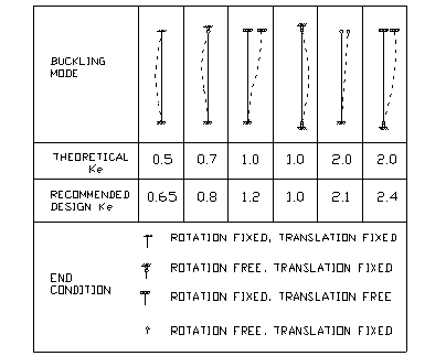
The slenderness ratio Le/d for solid column shall not exceed 50 for service load and shall not exceed 75 for construction. Le=Ke´L is effective length of column, Ke is slenderness ratio, L is unsupported length of column. For rectangular section, Le/d shall be evaluated in both directions.
-
Maximum compressive stress, fc must not exceed allowable stress parallel to grain, F’c = Fc*CD*CM*Ct*CF*Cp
Where
Fc is allowable bending stress in NDS supplement.
CD is load duration factor, (see beam design)
CM is wet service factor, (use when moisture of timber is higher than 19%)
Ct is temperature factor, (when timber is used in temperature higher than 150°F)
CF is size factor, (apply only to visually graded sawn lumber members, and to round timber bending members, not apply simultaneously with Cv for glued laminated timber)
Cp is column stability factor (see below)
Slenderness ratio, Ke

Column stability factor Cp
According to NDS 3.7.1, column stability factor shall be determined as
-
Fully supported laterally throughout its length, Cp=1.
-
Otherwise, Cp shall be calculated as
Fc*=Compressive design value in NDS tables multiplied by all other adjustment factor except Cp,
FcE= KcE´E’/(Le/d)2,
KcE=0.3 for visually graded lumber and machine evaluated lumber, (note: KcE=0.418 for machine stress rated lumber and glued laminated timber),
C=0.8 for sawn lumber, (note: c = 0.85 for round timber piles and 0.9 for glued laminated timber).
Design procedure for timber column and compressive members:
-
Select timber species and section.
-
Calculate slenderness ratio for both axes, Lex/dx, Ley/dy, where Lex=Lx*Kex, Ley=Ly*Key. Kex and Key, are slenderness ratios in x and y direction. Lx and Ly are unsupported length in x and y direction.
-
Determine maximum compressive stress, f”c=P/A. P is column axial load. A is cross section area.
-
Determine allowable compressive stress, Fc*
Fc* = Fc´CD´CM´Ct´CF
Where
Fc is allowable bending stress in NDS supplement.
CD is duration factor,
CM is wet service factor, (use when moisture of timber is higher than 19%)
Ct is temperature factor, (when timber is used in temperature higher than 150°F)
CF is size factor, (apply only to visually graded sawn lumber members, and to round timber bending members, not apply simultaneously with Cv for glued laminated timber)
-
Calculate elastic modulus
E'=E´CM´Ct
Where E is modulus of elasticity in NDS supplement
-
Calculate FcE= KcE*E'/(Le/d)2
-
Calculate Cp
-
Calculate allowable compressive stress,
F"c = Fc*´Cp
 Watch Videos
 Solved sample problems
 Download Files
 Read also
- Solved Example: Design of Sawn Timber Column
- Solved Example: Design of Timber Load Bearing Stud Wall
- Design of Sawn Timber Beams or Joists
- Solved Example: Design of 2x10 Timber Floor Joist with Southern Pine
- Solved Example: Design of 3-3x12 Timber Beam with Southern Pine
 Share
Share
Follow our official Facebook page (@civilengineeringbible) and Twitter page (@CivilEngBible) and do not miss the best civil engineering tools and articles!

