Types of concentric structural braces
Articles > Types of concentric structural bracesBraced frames may be grouped into two categories as either concentric braced frames (CBF) or eccentric braced frames (EBFs). In CBFs, the axes of all members, that is, columns, beams, and braces intersect at a common point such that the member forces are axial without signifcant moments. On the other hand, EBFs, utilize axis offsets to deliberately introduce flexure and shear in preselected beam segments to increase ductility.
Braced frames can take on many configurations some of which are shown in the figure. The diagonal member often consists of double angles, channels, tees, tubes or wide flange shapes, their selection frequently based on the ease of connection details.
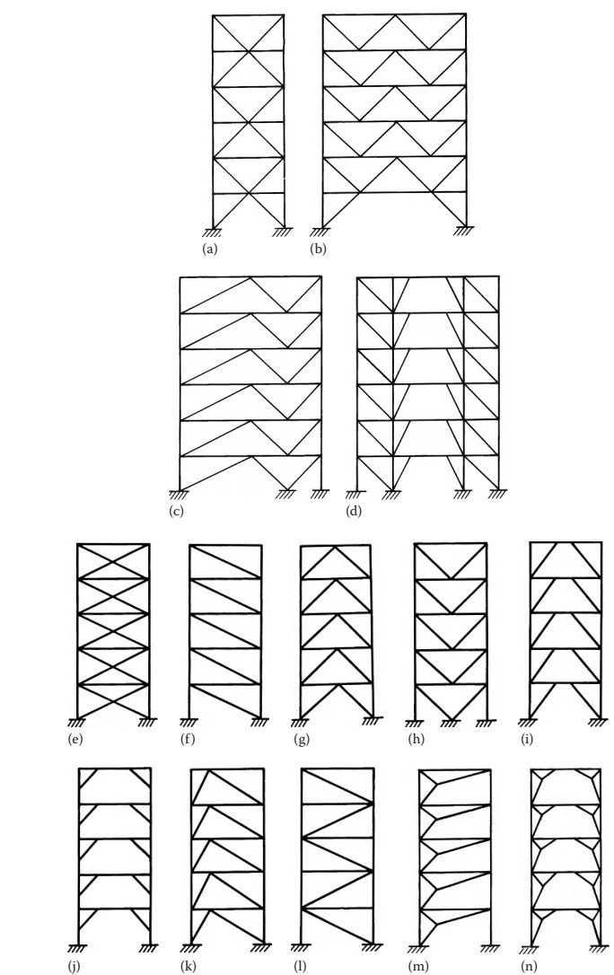
From architectural considerations, the least objectionable locations for braces are around service cores and elevators, where frame diagonals may be enclosed within permanent walls. The braces can be joined together to form a closed or partially closed three-dimensional cell for effectively resisting torsional loads. Any reasonable configuration with single or multiple braced bays, as shown in the figure, may be designed for resisting lateral loads. However, availability of proper depth for bracing is often an overriding consideration. As a preliminary guide, a height-to-width ratio of 8–10 is considered proper for a reasonably efficient bracing system.
Braced-frame systems tend to be more economical than moment-resisting frames when material, fabrication, and erection costs are considered. These effciencies are often offset by reduced flexibility in floor plan layout, space planning, and electrical and mechanical routing, encountered as a result of the space requirements for the brace members. Braced frames are, therefore, typically located in walls that stack vertically between floor levels. In a typical office building, these walls generally occur in the “core” area around stair and elevator shafts, central restrooms, and mechanical and electrical rooms. This generally allows for greater architectural flexibility in articulating vertical modulations of the building envelope. Depending on the plan location and the size of the core area of the building, the torsional resistance offered by the braced frames may become a controlling design parameter. Differential drift between stories at the building perimeter must be considered with this type of layout, as rotational displacements of the floor diaphragms may impose deformation demands on the cladding system and other nonstructural elements of the building.
 Read also:
- Types of eccentric braced frames
- Scaffolding Types in Construction
- Connections in Steel Structures
- Wood Shuttering Boards
- Retaining walls: Types and failure modes
 Share:
Follow our official Facebook page (@civilengineeringbible) and Twitter page (@CivilEngBible) and do not miss the best civil engineering tools and articles!