Elements of a Soil Nail Wall
Articles > Elements of a Soil Nail Wall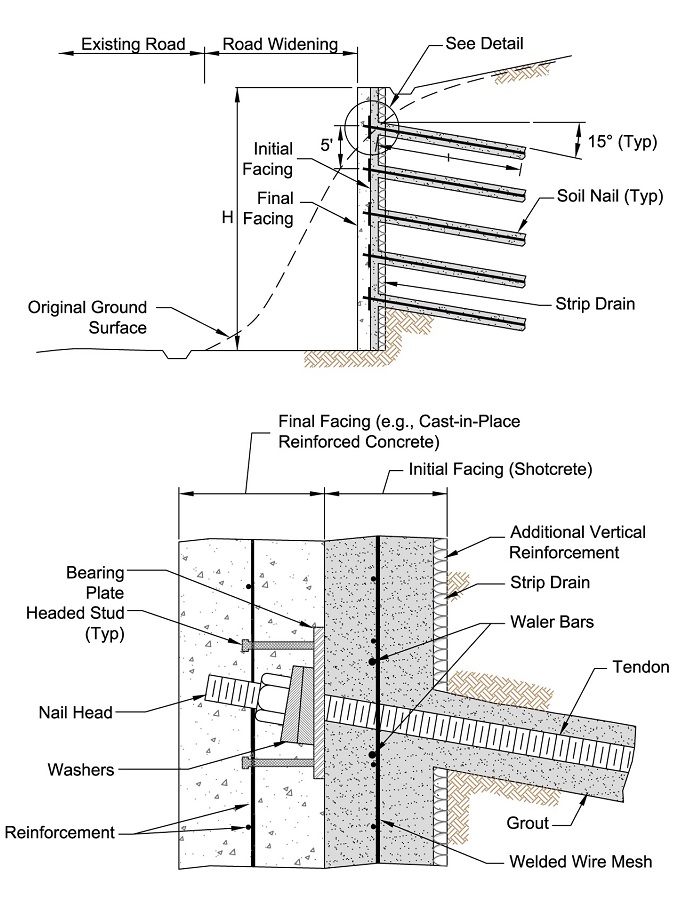
The components of soil nail walls used in the U.S. practice are identified in the figure and are briefly described below:
- Soil Nails
- Tendons – Tendons are the ground-reinforcing elements behind a soil nail wall and equivalent to (steel) bars. Tensile stress in each tendon mobilizes in response to lateral movement and deformation of the retained soil. Soil movement can occur during excavation, after excavation in the absence of external loads (as a result of time-dependent deformations), or after excavation when external loads such as surcharge or traffic loads are applied. The tendons can be solid or hollow bars. Solid bars are placed in stable drill holes and grouted in place. Hollow bars are fitted with a sacrificial drill bit and are used to drill the hole to then remain in place as the permanent soil nail reinforcement. Both solid and hollow bars are typically fully threaded.
- Grout – Grout used for soil nails usually consists of Portland cement and water. The grout functions to: (i) transfer shear stresses between the deforming ground and the tendons; (ii) transfer tensile stresses from the tendons to the surrounding stable soil; and (iii) provide some level of corrosion protection to the tendons. Grout is placed in the drill holes under gravity using the tremie method.
- Corrosion Protection – Soil nails used in permanent applications require chemical and/or physical protection against corrosion. The required level of corrosion protection is greater for soilswith higher corrosion potential and for projects with lower risk tolerance.
- The lowest level of corrosion protection in U.S. practice is provided by the grout alone. Encapsulation of the bar provides the highest level of corrosion protection and is achieved by adding a protective sheath and grouting the bars in a phased process. Corrosion protection of the soil nail tendon can also be provided by application of a fusion-bonded, epoxy coating, galvanization, or sacrificial steel.
- Facing
- Shotcrete – Facing consists of an initial and a final component. Soon after excavation, the initial facing is applied on the exposed soil at each excavation lift before or after nail installation to provide temporary stability and protection. The initial facing also receives the bearing plate of the soil nail. The final facing is constructed over the initial facing and provides structural continuity throughout the design life. The final facing may also include an aesthetic finish. The initial facing most commonly consists of reinforced shotcrete. The final facing generally consists of CIP-reinforced concrete, reinforced shotcrete, or precast concrete panels.
- Reinforcement used in the shotcrete of the initial facing includes the following items: (i) welded-wire mesh (WWM) installed over the entire excavation lift, and effectively over the entire wall using appropriate lap splices; (ii) horizontal bars (referred to as waler bars) placed around nail heads to add bending resistance in the horizontal direction; and (iii) vertical bearing bars placed at nail heads to add bending resistance in the vertical direction(see the figure). Other reinforcement options include the use of steel or synthetic fiber particularly fortemporary facing in soft or weathered rock. If the final facing consists of shotcrete, the reinforcement in the final facing is similar to that described for shotcrete in the initial facing. If the final facing consists of CIP or precast concrete, rebar mesh is typical.
- Other Components
- Connection Components – The soil nail is connected to the facing through a number of components including: nuts, washers, bearing plates, and headed-studs. The headed studs are attached to the bearing plate and become embedded within the final facing as depicted in the figure.
- Drainage System – A drainage system is installed behind soil nail walls to: (i) collect perched groundwater or infiltrated surface water that is present behind the facing; and (ii) direct the collected groundwater away from the wall. The drainage system commonly consists of composite, geosynthetic drainage strips, also referred to as geocomposite strip drains. The drainage system does not provide full coverage of the wall area, but rather covers commonly 10-20%, or more, of the excavation face, depending on the selected strip drain spacing and commercial widths that are available.
 Read also:
- Advantages and Limitations of Soil Nailing
- Applications of Soil Nail Walls
- Construction Sequence of a Soil Nail Wall
- Origins and History of Use and Development of Soil Nails in the United States
- Unfavorable or Difficult Soil Conditions for Soil Nailing
 Share:
Follow our official Facebook page (@civilengineeringbible) and Twitter page (@CivilEngBible) and do not miss the best civil engineering tools and articles!