Shaft Resistance of Piles
Courses > Foundation Analysis and Design > Bearing Capacity of Piles (Deep Foundations) > Shaft Resistance of Piles Introduction
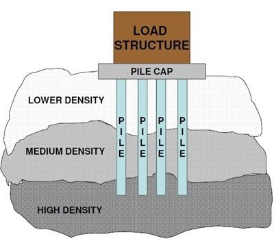
A deep foundation is a type of foundation which transfers building loads to the earth farther down from the surface than a shallow foundation does, to a subsurface layer or a range of depths.
A pile is typically a vertical structural element of a deep foundation, driven or drilled deep into the ground at the building site.
Ultimate bearing capacity of piles is the sum of its skin resistance and tip resistance:
where Q tip,ult = tip resistance; QsL = skin resistance; qtip-ult = bearing stress; Ab = area of pile tip; qsi = skin friction of ith layer; Asi = skin area in contact with ith layer;
 Concepts and Formulas
There are numerous methods that have been used over the years to estimate shaft resistance. A few of these methods are illustrated in this section.
Granular Soils and Drained Clays (Long-term clays):
K-δ Method:
K and δ are usually estimated based on the type of pile and the characteristics of the soil.
Here are some methods to estimate these two parameters.
â–º Estimate K:
1- Stas and Kulhawy method:
| Foundation type and methd of installation | Ratio of horizontal soil stress coefficient to in-situ value, K/K0 |
|---|---|
| Jetted pile | 1/2 to 2/3 |
| Drilled shaft, cast-in-place | 2/3 to 1 |
| Driven pile, small displacement | 3/4 to 5/4 |
| Driven pile, large displacement | 1 to 2 |
2- Sowers method:
| Foundation type | Ratio of horizontal soil stress coefficient to in-situ value, K/K0 | |
|---|---|---|
| Loose sand (Dr < 30%) | Dense sand (Dr > 70%) | |
| Jetted piles | 0.5 to 0.75 | 0.5 to 1.0 |
| Drilled piles | 0.75 to 1.5 | 1 to 2 |
| Driven piles | 2 to 3 | 3 to 4 |
â–º Estimate δ
1- Stas and Kulhawy method:
| Interface materials | Ratio of interface angle of friction to soil angle of friction δ/φ | Typical field analogy |
| sand/rough concrete | 1.0 | cast-in-place |
| sand/smooth concrete | 0.8 to 1.0 | precast |
| sand/rough steel | 0.7 to 0.9 | corrugated |
| sand/smooth steel | 0.5 to 0.7 | coated |
| sand/timber | 0.8 to 0.9 | pressure-treated |
Undrained Saturated Clays (Short-term clays):
alpha method:
obtain α using the following equation from Kulhawy
where Pa = atmospheric pressure; Su = undrained shear strength
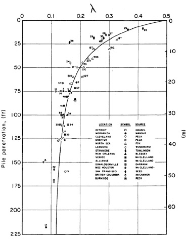
lambda method:
where q is the mean effective vertical stress over the embedded pile length and λ is obtained from the figure below (from Kulhawy). According to Kulhawy, the values of λ shown in the figure below are valid only for steel pipe piles. Limited research has shown that λ for drilled shafts (typically less than 20 ft deep) is on the order of about 1/3 to 2/3 of the values shown in the figure below.
Direct Estimates from In Situ Tests:
From the CPT test, pile shaft resistance can be determined from either the sleeve friction (fs) or the tip resistance (qc):
where ρ is the friction ratio. For driven piles, the value of rho can be estimated from either of the following equations:
or
Values of ρ for drilled shafts are 1/3 to 1/2 the values shown in the two equations above.
Meyerhof recommended the following equations for shaft resistance in high and low
displacement piles:
High displacement piles:
Low displacement piles:
For driven piles in sand, Briaud suggested that:
 Watch Videos
 Solved sample problems
 Download Files
 Read also
- Everything about sheet-pile walls: types, materials and construction methods
- Spillways and their types
- Top software for Geotechnical Engineers
- Ultimate Tip Resistance of Piles
- Anchored Sheet Pile Walls Penetrating Sandy Soils
 Share
Share
Follow our official Facebook page (@civilengineeringbible) and Twitter page (@CivilEngBible) and do not miss the best civil engineering tools and articles!