Shear Design of Reinforced Concrete Beams
Courses > Reinforced Concrete Design > Design of Concrete Members > Shear Design of Reinforced Concrete Beams Introduction
Design shear stresses generally act along planes perpendicular to the longitudinal axis of a member. These stresses, either alone or in combination with normal stresses, create principal tensile stresses that can lead to sudden failure. ACI design criteria alleviate the risk of such failures by applying more conservative theories and resistance factors than are used for more ductile modes of failure.
In the following sections, the ACI 318 shear provisions are summarized and illustrated for some of the more commonly encountered design cases.
 Concepts and Formulas
Shear Strength of Slender Reinforced Concrete Beams
The basic strength requirement for shear design is

or
.jpg)
Vu is the shear caused by the factored loads, Vn is the nominal shear strength of the member, Vc is the contribution of concrete to shear resistance, Vs is the contribution of shear reinforcement to shear resistance, and φ is the capacity reduction factor, which is 0.75.
The following step-by-step guide summarizes the ACI 318 shear design provisions that apply to the most commonly encountered case, in which the slender reinforced concrete beam is subject to the following restrictions.
- The span-to-depth ratio is greater than or equal to four.
- The beam is supported and loaded such that the reaction induces compression in the region near the support.
- The beam is transversely loaded by static forces so that the torsion and axial forces caused are negligible.
- Only vertical leg stirrups are used, and their total cross-sectional area is Av.
- The simpler expression for the contribution of the concrete to shear resistance is used.
What is the step-by-step procedure for shear design of concrete members?
1- compute design shear force, Vu, at appropriate location
2- compute Vc using simple equation ACI 11-3:

where l = 1 for normal weight concrete; 0.85 sand-lightweight concrete ; 0.75 for all-lightweight concrete.
3- Check

3-1- if Yes â–º no stirrups required
3-2- if No â–º

4- Check

4-1- if Yes â–º STOP and use min. stirrups required:

4-2- if No â–º

5- Check

5-1- if Yes â–º web crushes: STOP and redesign beam
5-2- if No â–º Check

5-2-1 if Yes â–º

and

5-2-2 if No â–º

and
Comprehensive textbooks on reinforced concrete treat more general cases involving deep beams, beams with axial forces or torsion, or inclined shear reinforcement.
Shear Friction
There are many situations in which shear force is transferred from one concrete element to another or between a concrete element and another material. A model has been developed that has been shown to correlate with the nominal strength of this force transfer. This model is analogous to static friction with a normal force provided by properly developed reinforcement that crosses the shear plane, modified by an appropriate coefficient of static friction, μ.
ACI Sec. 11.6.4 defines the coefficient of friction as follows:
- For concrete placed monolithically, μ = 1.4λ.
- For concrete placed against hardened and deliberately roughened concrete, with surface clean and roughened to a minimum amplitude of 1/4 in, μ = 1.0λ.
- For concrete placed against hardened concrete cleaned of laitance, but not roughened, μ = 0.6λ.
- For concrete placed against as-rolled, unpainted structural steel, μ = 0.7λ.
The constant λ is 1.0 for normal weight concrete, 0.85 for sand-lightweight concrete, and 0.75 for all lightweight concrete.
When shear friction reinforcement with an area of Avf crosses the shear plane at right angles, which is the usual case, the nominal shear strength is
A_c \end{matrix}\right..jpg)
fy, the yield strength of reinforcement, is limited to a maximum of 60,000 psi. Ac is the area of the concrete section resisting shear. ACI 318 also gives a more general expression for shear transfer when tensile shear friction reinforcement crosses the shear plane at an acute angle.
Brackets and Corbels
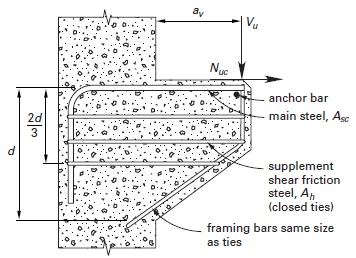
A bracket or corbel is a reinforced concrete element that projects from a wall or column and supports a reaction from another element. In most cases, the reaction is primarily a vertical force whose resultant acts at a short distance av from the face of the supporting wall or column, as shown in the figure below. Unless special provisions are made to alleviate horizontal forces (for example, by using very low friction-bearing pads or roller supports), there will also be a horizontal tensile force, Nuc, transmitted into the support. ACI Sec. 11.8.3 requires that the horizontal force be treated as a live load with a magnitude of at least 20% of the vertical force, Vu. For most practical cases, when the ratio av/d is less than 1, the prescriptive procedure in Sec. 11.8 of ACI 318 is used to design the bracket or corbel.
The following restrictions apply:
- The yield strength of reinforcement, fy, must not exceed 60,000 psi.
- The horizontal tensile force, Nuc, must not be less than 0.2Vu or greater than Vu.
- The effective depth, d, is determined at face of support.
- The main reinforcement, with an area of Asc, must fully develop at face of support. This usually requires mechanical anchorage of the main steel, either by welding a cross bar of the same diameter or by welding to steel plates.
- The depth at the outside edge of bearing must be not less than 0.5d.
- The capacity reduction factor, φ, is 0.75 in all calculations.
- Shear transfer occurs through shear friction.
- Supplementary shear friction steel in the form of closed ties is distributed over the upper 2d/3 of the member.
What is the step-by-step prescriptive design provisions in ACI 318 for a bracket or corbel?
1- Given Vu, Nuc, fy, f'c, unit wieght λ,h, b=bw, d, av, φ=0.75, μ:
2- Check if it is normal weight concrete
2-1- if Yes â–º
b_wd\ 1600b_wd \end{matrix}\right..jpg)
2-2- if No â–º
f-_cb_wd\ (800-\frac{280a_v}{d})f-_cb_wd \end{matrix}\right..jpg)
3- Check

3-1- if Yes â–º
3-2- if No â–º continue to step 4
4-
.jpg)
}.jpg)


5-
main (top) steel:
bd \end{matrix}\right..jpg)
supplemental shear friction steel
.jpg)
Torsion
Most reinforced concrete members are loaded either axially or transversely in such a manner that twisting of the cross section is negligible. ACI Sec. 11.5 sets threshold limits for torsional moments beyond which their effects must be included in designs. From ACI Sec. 11.5.1, for nonprestressed members, the threshold limit is
.jpg)
Tu is the factored torsional moment, Acp is the area of the outside perimeter of section resisting torsion, pcp is the outside perimeter of the section resisting torsion.
If the applied factored torsional moment exceeds the threshold, the member must be reinforced with additional transverse ties and longitudinal steel to resist the torsional moment. ACI 318 considers two cases: equilibrium torsion and compatibility torsion.
Equilibrium torsion applies to situations where redistribution of loads cannot occur and the torsional resistance is necessary to maintain equilibrium. A common example is a precast concrete spandrel beam. Compatibility torsion describes a situation in which loads can redistribute after torsional cracking. In such a case, a reduction is permitted in the design value of torsional moment. In the case of compatibility torsion, ACI Sec. 11.5.2 allows the maximum torsional moment that the member must be designed to carry to be limited to four times the threshold value.
For the precast beam, full torsional resistance is needed to maintain equilibrium and this member must be designed for equilibrium torsion. In contrast, for the cast-in-place spandrel, a reduction in torsional resistance reduces the negative bending moment transferred from the slab with a corresponding redistribution of moment to the positive region of the slab. This is a case of compatibility torsion.
Design for torsion is performed using a space truss model and assuming an equivalent hollow tube, compression diagonals developing in the concrete at 45â—¦ to the longitudinal axis, and longitudinal and transverse steel resisting all tension. The ties must be closed, with details defined in ACI Sec. 11.5.4. The transverse steel needed to resist torsion is additive to the stirrups resisting shear. Because only the outer legs of the stirrups provide torsional resistance, the transverse steel required is
.jpg)
s is the spacing, Av is the area of outer stirrup legs resisting shear, and At is the required area of one outer leg to resist torsion. The space truss analogy also requires longitudinal steel, Al, that is generally additive to any other longitudinal steel required to resist axial forces or bending. ACI Sec. 11.5.6.2 requires that the longitudinal torsional steel must be distributed around the perimeter resisting torsion at a spacing of no more than 2 in. The design procedure for both transverse and longitudinal reinforcement for members with torsional moment, Tu, exceeding the threshold is summarized below:
What is step-by-step design prodecure for both transverse and longitudinal reinforcement for members with torsional moment, Tu, exceeding the threshold of Sec 11.5.1?
1- take θ=45, A0=0.85Aoh
2- Check
-2-(\frac{T_uP_h}{1.7A-2_{oh}})-2}\leq\phi (\frac{V-c}{b_wd}-8\sqrt{f-_c}).jpg)
2-1- if No â–º compression struts control; STOP and redesign section
2-2- if Yes â–º
f_{yt}cot45}-\frac{T_u}{\phi (2A_o)f_{yt}}.jpg)
3- Check

3-1- if No â–º

3-2- if Yes â–º continue to step 4
4- Avo = total area in outer legs of closed stirrups
.jpg)
5- Check

4-1- if No â–º

4-2- if Yes â–º continue to step 6
6-
p_h(\frac{f_{yt}}{f_y})cot-245.jpg)
7- Check

7-1- if No â–º

7-2- if Yes â–º continue to step 8
8- Check
p_h(f_{yt}/f_y).jpg)
8-1- if No â–º
p_h(f_{yt}/f_y).jpg)
8-2- if Yes â–º End
 Watch Videos
 Solved sample problems
 Download Files
 Read also
- Reinforced Concrete Beam Design
- Difference Between RCC and Prestressed Concrete
- Solved Example: Design of 2x10 Timber Floor Joist with Southern Pine
- Solved Example: Design of 3-3x12 Timber Beam with Southern Pine
- Solved Example: Design of 2x12 Timber Floor Joist with Douglas Fir-Larch
 Share
Share
Follow our official Facebook page (@civilengineeringbible) and Twitter page (@CivilEngBible) and do not miss the best civil engineering tools and articles!