Flexural Design of Reinforced Concrete Beams
Courses > Reinforced Concrete Design > Design of Concrete Members > Flexural Design of Reinforced Concrete Beams Introduction
Flexural members are slender members that deform primarily by bending moments caused by concentrated couples or transverse forces. In modern construction, these members may be joists, beams, girders, spandrels, lintels, and other specially named elements. But their behavior in every case is essentially the same. Unless otherwise specified in a problem, flexural members will be referred to as beams here. In the following sections, the ACI 318 provisions for the strength, ductility, serviceability, and constructability of beams are summarized and illustrated.
 Concepts and Formulas
Strength
The basic strength requirement for flexural design is
Mn is the nominal moment strength of the member, Mu is the bending moment caused by the factored loads, and φ is the capacity reduction factor. For most practical designs, ACI specifies the value of φ as 0.9; however, special cases exist for which lower values apply.
Mn for a Singly Reinforced Concrete Beam
The simplest case is that of a rectangular beam containing steel in the tension zone only. A beam of this sort is referred to as singly reinforced. Figure below shows a typical cross section of a singly reinforced beam and the notation used.
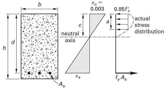
ACI Secs. 10.2 and 10.3 give the principles governing the flexural strength.
- Strain varies linearly through the depth of the member.
- A complete bond exists between the steel and the concrete; that is, the strain in the steel is the same as in the adjacent concrete.
- Tension stress in the concrete is negligible (that is, all tension is resisted by steel).
- The ultimate strain in concrete is 0.003.
- In a properly designed beam, the tension steel yields; thus, T = Asfy.
- The concrete stress distribution may be replaced by an equivalent rectangular distribution with uniform stress 0.85f'c acting over an area ba and creating a compression resultant, C = 0.85f'cba, that acts at distance a/2 from the compression edge.
For bending without axial force applied, equilibrium requires
The resultant compression force in the concrete, C, forms a couple with the resultant tension force, T.
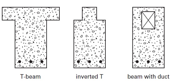
Beams with Irregular Cross Sections
Many reinforced concrete beams have cross sections that are not rectangular. Figure below shows three typical cross sections with irregularly shaped compression regions.
Fortunately, the same principles that govern the behavior of rectangular beams apply more generally to these cases as well. In the absence of axial forces, in a properly designed beam (that is, a beam for which tension steel yields) the compression region is determined using the condition of equilibrium.
Geometric relationships determine the depth of compression region and a summation of moments gives the nominal moment strength of the section.
Example: Solution of Design Moment Strength of An Irregularly Shaped Beam Section
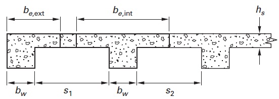
For most cast-in-place floor systems, the slab and beams are cast monolithically and the slab functions as the flange of a T- or L-shaped beam, as shown in Figure below. ACI Sec. 8.12 limits the effective flange width, be, of such members by the following criteria.
Slab Extending Both Sides (T-Beam):
Slab Extending One Side Only (L-Beam):
L is the span. Other symbols are as defined in figure below.
Ductility Criteria
ACI Secs. 10.3.5 and 10.5 limit both the minimum and maximum amount of tension steel that is acceptable in a beam. The minimum limit ensures that the flexural strength of the reinforced beam is appropriately larger than that of the gross section when it cracks. This requires
The code makes an exception to this requirement for slabs and footings, which require minimum temperature and shrinkage steel, and for special cases in which the amount of steel provided in a flexural member is at least one-third greater at every point than required by analysis. For cantilevered T-beams with the flange in tension, the value of bw used in the expressions is the smaller of either the flange width or twice the actual web width.
The maximum limit on the amount of tension steel ensures that the steel yields well before the concrete crushes, so that the beam fails in a gradual, ductile manner and not a sudden, brittle manner. This provides warning in the event of failure. ACI Sec. 10.3.5 limits the strain in the extreme tension reinforcement at the nominal strength. For sections subject to bending
with negligible axial force (axial force less than 0.1f'cAg), the strain in the extreme tension steel must exceed 0.004 (that is, approximately twice its yield strain) when the extreme compression edge of the member reaches the ultimate concrete strain of 0.003.
However, the code imposes a capacity reduction factor of 0.65 when the strain in the tension steel equals 0.002. The capacity reduction factor increases linearly to a maximum value of 0.9 as the tension strain increases from 0.002 to 0.005. There is rarely a practical advantage to designing beams for which the tension strain is less than 0.005, so this limit, which permits a capacity reduction factor of 0.9.
Design of Singly Reinforced Rectangular Beams
The design of a singly reinforced rectangular beam to resist a factored bending moment requires solving for appropriate dimensions and tension reinforcement. In practical problems, the specified compressive strength and yield strength of the reinforcement are known. When the dimensions b and d are known, the solution for As is a straightforward solution of the equation
The calculated As must satisfy the ductility limits imposed by As,min and As,max.
Design Equation in Terms of the Steel Ratio
In many cases, it is more convenient to express the moment strength of a singly reinforced section in terms of the nondimensional steel ratio, ρ, defined as
In terms of the steel ratio, the equations for moment strength, minimum steel, and maximum steel are
The steel area is determined uniquely when the dimensions of the member are known. However, if one of the dimensions b or d is unknown, an infinite number of combinations of steel area and beam dimensions will satisfy the strength requirement. In these cases, it is necessary to select a feasible steel ratio and solve the problem. The best choice for the steel ratio is that which satisfies construction and economic constraints. In the absence of specific directions, a reasonable approach is to select a steel ratio midway between the minimum and maximum permitted.
Doubly Reinforced Beams
When longitudinal reinforcement exists near the compression edge of a beam as well as in the tension region, a beam is doubly reinforced. Reinforcement near the compression edge is most often due either to construction requirements (such as when bars are placed to support shear reinforcement) or to a situation where the surface may be in tension and in compression at different times and from different loads. In these cases, the steel near the compression edge is usually ignored, as it contributes very little to the flexural strength of the beam.
There are cases, however, when the compression steel is added in order to add one or more of the following.
- compression resistance when beams are compression controlled as singly reinforced members
- stiffness to improve immediate and long-term deflection behavior
- ductility
In these cases, the section is usually analyzed to assess the effect of the additional reinforcement. To find a moment strength that satisfies strain compatibility, stress-strain relationships, and equilibrium, a trial-and-error process is used. This leads to a solution in a few iterations.
The principles are the same as the one mentioned earlier, with one additional assumption given in ACI Sec. 10.2.4: Stress in steel is Es times the steel strain when the strain is below yield, and is equal to the yield stress for all strains greater than yield. The additional notation involved is shown in Figure below, where A's is the area of steel near the compression edge and d' denotes the distance from compression edge to centroid of this steel.

Construction Considerations
There is generally more than one way to select reinforcement to furnish the required steel area. Certain criteria related to crack control and development of reinforcement—discussed in later sections—may influence the choice. However, the constraint that usually controls the choice is that the spacing of the reinforcement bars must provide for reasonable consolidation of the concrete.
The limits on bar spacing for beams and girders are contained in ACI Secs. 3.3 and 7.6. The clear spacing between adjacent bars must be
Here, s is the clear spacing and db is the nominal bar diameter. In some cases, restrictions on beam width make it impractical to use separate bars and the code permits bars to be bundled in groups of two, three, or four bars in contact. For bundled bars, the nominal diameter used in the spacing limit is that of a fictitious round bar with the same area as the total areas of bars in the bundle.
 Watch Videos
 Solved sample problems
- Solution of Maximum Uniformly Distributed Service Live Load That A Beam Can Support Based on Its Flexural Strength
- Solution of Design Moment Strength of An Irregularly Shaped Beam Section
 Download Files
 Read also
- Solution of Maximum Uniformly Distributed Service Live Load That A Beam Can Support Based on Its Flexural Strength
- Serviceability of Reinforced Concrete Beams
- Solution of Design Moment Strength of An Irregularly Shaped Beam Section
- Steel Quiz (10 Short-Answer Questions)
- Reinforced Concrete Beam Design
 Share
Share
Follow our official Facebook page (@civilengineeringbible) and Twitter page (@CivilEngBible) and do not miss the best civil engineering tools and articles!