What is the difference between plate girder and gantry girder?
Articles > What is the difference between plate girder and gantry girder?Plate Girders:
The typical I beam when made up from different structural steel plates/section instead of single rolled steel cross-section, which is welded or bolted or riveted together so that vertical web and horizontal flanges of the beam, this section is called as plate girders. The plate girder bridges are generally suitable for the shorter span to medium span and support highways, railroads or other types of traffic. If the larger span (over 20 m) is to be provided with the plate girders then the plate girders should be combined with the extra cover plates.
The plate girder has good flexural strength while the resistance to bending as well as shear may be increased by increasing the distance between the flanges. The web plate consists of thin steel plate which may buckle under the load; this can be prevented if the web stiffeners in horizontal and vertical direction are provided.
When the welding technology was not available at that time the practice was to use riveted or bolted plate girders. Earlier many bridges of span varying from 24 m to 46 m were built in this connection. While nowadays the welded plate girders are built, it aesthetically looks good and light in weight when compared to other connection like bolted/riveted plate girders.
Components of plate girder:
The plate girder consists of following components:
- The web plate
- Flange plate (addition of cover plate curtailed at proper sections)
- Stiffeners like bearing stiffeners, longitudinal stiffeners, and intermediate stiffeners
- Splices for flange plate and web plate
- End connections
Web plate:
The web plates are provided so that the beam can resist the shear acting on it. The thickness of the web plate varies from 8 mm to 15 mm. The depth of the web plate depends upon the type and quantity of loading. The depth of web of plate girder may vary from 1/8th to 1/12th of the span. This may be in the range of 1000 mm for the case of the smaller span as well as 2500 mm for the larger span. If the depth required is larger, it may be stiffened with the help of load-bearing stiffener under the loading, also the intermediate stiffeners and longitudinal stiffeners can also be provided to get the stable plate girders.
Flange plates:
The flange plates of plate girder are provided to resist the bending moment which will be acting on the beam by developing the compressive force in one flange and tensile force in other flange. The extra plate may be provided in case of the very large bending moment. The plate girder is also curtailed at proper sections to make the lighter section and therefore the economy is achieved. The stiffeners, web and flange if properly connected with the welding or bolting or riveting connections then the structure of plate girders will be formed.
Stiffeners:
The stiffeners are provided at the different location and accordingly, it has the names like load bearing stiffeners, longitudinal stiffeners, end bearing stiffeners and intermediate stiffeners.
Gantry girder:
There is the difference between the plate girder and gantry girder as both have different properties while selecting as a member in the industrial structure. The capacities of both plate girder and gantry girder are also different according to the different elements connected.
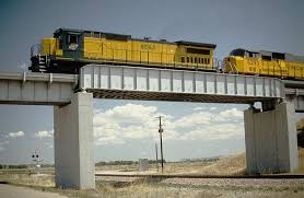
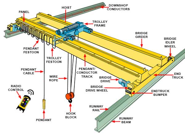
In factories and workshops, overhead traveling cranes are generally used to lift the heavy materials, equipments, etc and also to carry it from one place to another. Such types of cranes are mostly hand driven or electrically operated. The crane mostly consists of the bridges which have the span at the bay of the shop. The trolley or some type of cab is generally mounted on the bridge. Then the bridge as the whole unit moves longitudinally on the rails which are provided at the ends.
The rail on either side of the bridge rests on the crane gantry girder. The gantry girders are girders which supports the loads that are transmitted through the traveling wheels of the crane.
The crane girder spans from column to column, this usually do not have any lateral support at the intermediate points excepting when a walkway is formed at the top of the girder. Therefore under normal circumstances, the crane girder should be designed as laterally unsupported beam carrying vertical as well as the horizontal load at the top flange. So, the girder should be provided but having very heavy and wide compression flange is necessary. The wide flange beam without any other reinforcement is used for the shorter span and light crane loads. The cover plate should be provided on the compression face so that the lateral buckling strength of the beam improves while larger moment of inertia about the vertical axis against any lateral loading is also provided. To increase the property of Iyy then the channel can be provided instead of the cover plate. To increase the torsional stiffness of the girder channel is provided just below the compression flange of the wide flange beam and supported by brackets.
The stresses in the fiber of gantry crane girders should be computed by considering the bi-axial bending combined with the torsion. Generally the torsion is produced by the lateral force which applied at the top flange. The lateral moment is resisted by the top flange bending horizontally without any assistance from the bottom flange. The crane girders are supported on brackets which are connected to columns of uniform sections, it can also rested on stepped columns. The stepped columns are used for heavy crane loads and taller columns while the brackets are used for lighter crane loads. To restrain from lateral bending and twisting at the support point the girder is supported on suitably formed seat which are connected to the column just near the top flange. Also due to effect of temperature and deflection, to permit the horizontal movement in the crane girder slotted holes are used to connect the channels with column. To provide the restraint the vertical plates are mostly provided in the crane girder. If the roof leg as well as the crane leg is of column load and the shear action due to the effect of bending under crane load and wind load.
The crane columns should be properly braced in the longitudinal direction of the crane girder so that it can take the longitudinal forces acting due to moving crane. This kind of bracing should be provided at every fourth or fifth bay, while the other bays should be provided with the struts to transmit the longitudinal force to the bracing frame.
 Read also:
- What are beam bridges? Types and Structural elements of a beam bridge
- Arch Bridges: Types, Elements, and List of 10 world longest arch bridges
- Wood Shuttering Boards
- Which type of earthing is more advantageous?
- How do Cantilever bridges function? Ten longest cantilever bridges around the world
 Share:
Follow our official Facebook page (@civilengineeringbible) and Twitter page (@CivilEngBible) and do not miss the best civil engineering tools and articles!