Solved Example: Design of A Steel Moment Frame by Effective Length Method Per AISC (ASD & LRFD)
Articles > Solved Example: Design of A Steel Moment Frame by Effective Length Method Per AISC (ASD & LRFD)Question:
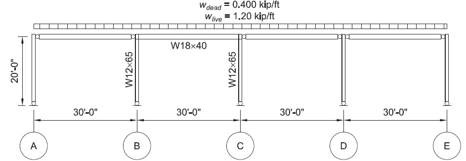
Determine the required strengths and effective length factors for the columns in the rigid frame shown below for the maximum gravity load combination, using LRFD and ASD. Use the effective length method. All members are ASTM A992 material.
Columns are unbraced between the footings and roof in the x- and y-axes and are assumed to have pinned bases.
Solution:
Read also: solution to the same problem using Direct Analysis Method per AISC.
The W12x65 has Ix = 533 in4.
The beams from grid lines A to B, and C to E and the columns at A, D and E are pinned at both ends and do not contribute to the lateral stability of the frame. There are no P-Δ effects to consider in these members and they may be designed using K=1.0.
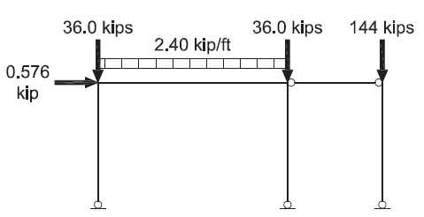
The moment frame between grid lines B and C is the source of lateral stability and therefore must be designed using the provisions of Appendix 7 of the AISC Specification. Although the columns at grid lines A, D and E do not contribute to lateral stability, the forces required to stabilize them must be considered in the analysis. For the analysis, the entire frame could be modeled or the model can be simplified as shown in the figure below, in which the stability loads from the three “leaning” columns are combined into a single column.
Check the limitations for the use of the effective length method given in Appendix 7, Section 7.2.1:
- The structure supports gravity loads through nominally vertical columns.
- The ratio of maximum second-order drift to the maximum first-order drift will be assumed to be no greater than 1.5, subject to verification following.
From Chapter 2 of ASCE/SEI 7, the maximum gravity load combinations are:
| LRFD | ASD |
|---|---|
| wu = 1.2D + 1.6L = 1.2(0.400 kip/ft) + 1.6(1.20 kip/ft) = 2.40 kip/ft |
wa = D + L = 0.400 kip/ft + 1.20 kip/ft = 1.60 kip/ft |
Per AISC Specification Appendix 7, Section 7.2.1, the analysis must conform to the requirements of AISC Specification Section C2.1, with the exception of the stiffness reduction required by the provisions of Section C2.3.
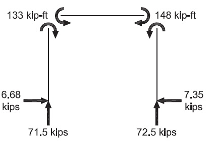
Per AISC Specification Section C2.1, for LRFD perform a second-order analysis and member strength checks using the LRFD load combinations. For ASD, perform a second-order analysis at 1.6 times the ASD load combinations and divide the analysis results by 1.6 for the ASD member strength checks.
Frame Analysis Gravity Loads
The uniform gravity loads to be considered in a second-order analysis on the beam from B to C are:
| LRFD | ASD |
|---|---|
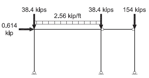
| w'u = 2.40 kip/ft | wa' = 1.6(1.60 kip/ft) = 2.56 kip/ft |
Concentrated gravity loads to be considered in a second-order analysis on the columns at B and C contributed by adjacent beams are:
| LRFD | ASD |
|---|---|
| Pu' = (15.0 ft)(2.40 kip/ft) = 63.0 kips |
Pa' = 1.6(15.0 ft)(1.60 kip/ft) = 8.34 kips |
Concentrated Gravity Loads on the Pseudo “Leaning” Column
The load in this column accounts for all gravity loading that is stabilized by the moment frame, but is not directly applied to it.
| LRFD | ASD |
|---|---|
| PuL' = (60.0 ft)(2.40 kip/ft) = 144 kips |
PaL' = 1.6(60.0 ft)(1.60 kip/ft) = 154 kips |
Frame Analysis Notional Loads
Per AISC Specification Appendix 7, Section 7.2.2, frame out-of-plumbness must be accounted for by the application of notional loads in accordance with AISC Specification Section C2.2b.
From AISC Specification Equation C2-1, the notional loads are:
| LRFD | ASD |
|---|---|
| α = 1.0 Yi = (120 ft)(2.40 kip/ft) = 288 kips Ni = 0.002αYi (Spec. Eq. C2-1) = 0.002(1.0)(288 kips) = 0.576 kips |
α = 1.6 Yi = (120 ft)(1.60 kip/ft) = 192 kips Ni = 0.002αYi (Spec. Eq. C2-1) = 0.002(1.6)(192 kips) = 0.614 kips |
Summary of Applied Frame Loads
| LRFD | ASD |
|---|---|
 |
 |
Per AISC Specification Appendix 7, Section 7.2.2, conduct the analysis using the full nominal stiffnesses.
50% of the gravity load is carried by the columns of the moment resisting frame. Because the gravity load supported by the moment resisting frame columns exceeds one third of the total gravity load tributary to the frame, per AISC Specification Section C2.1, the effects of P-δ must be included in the frame analysis. If the software used does not account for P-δ effects in the frame analysis, this may be accomplished by adding joints to the columns between the footing and beam.
Using analysis software that accounts for both P-Δ and P-δ effects, the following results are obtained:
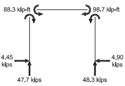
First-order results
| LRFD | ASD |
|---|---|
|
Δ1st = 0.119 in.
|
Δ1st = 0.127 in. (prior to dividing by 1.6)
|
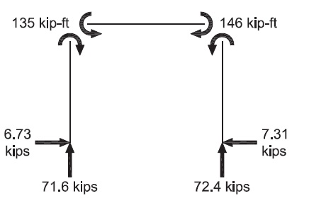
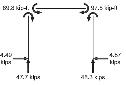
Second-order results
| LRFD | ASD |
|---|---|
|
Δ2nd = 0.159 in.
|
Δ2nd = 0.174 in. (prior to dividing by 1.6)
|
The assumption that the ratio of the maximum second-order drift to the maximum first-order drift is no greater than 1.5 is verified; therefore, the effective length method is permitted.
Although the second-order sway multiplier is approximately 1.35, the change in bending moment is small because the only sway moments for this load combination are those produced by the small notional loads. For load combinations with significant gravity and lateral loadings, the increase in bending moments is larger.
Calculate the in-plane effective length factor, Kx, using the “story stiffness method” and Equation below (from C-A-7-5 presented in AISC Specificaion Appendix 7, Section 7.2). Take Kx = K2
Calculate the total load in all columns,
| LRFD | ASD |
|---|---|
Calculate the ratio of the leaning column loads to the total load, RL
| LRFD | ASD |
|---|---|
Calculate the Euler buckling strength of an individual column.
Calculate the drift ratio using the first-order notional loading results.
| LRFD | ASD |
|---|---|
For the column at line C:
| LRFD | ASD |
|---|---|
|
User Kx = 3.13 |
User Kx = 3.13 |
Note that it is necessary to multiply the column loads by 1.6 for ASD in the expression above.
Verify the column strengths using the second-order forces shown above, using the following effective lengths (calculations not shown):
Columns:
Use KxLx = 3.13(20.0ft) = 62.6ft
Use KyLy = 20.0 ft
 Read also:
- Solved Example: Design of A Steel Moment Frame by Direct Analysis Method Per AISC (ASD & LRFD)
- AISC 341-05 requirements for special plate shear walls
- Steel Quiz (10 Short-Answer Questions)
- Solved Example: Analysis of a welded steel beam-to-column connection (BS 5950)
- Solved Example: Analysis of a one-way spanning unreinforced masonry wall panel (BS 5628)
 Share:
Follow our official Facebook page (@civilengineeringbible) and Twitter page (@CivilEngBible) and do not miss the best civil engineering tools and articles!