Deep Compaction Techniques
Articles > Deep Compaction TechniquesDensification of deep soil deposits is achieved by following techniques:
- Pre-compression, or pre-loading
- Explosion
- Heavy tamping
- Vibration
- Compaction grouting
- Vibro-compaction and vibro-replacement
Pre-compression
A site is pre-loaded by means of a surcharge or by lowering the groundwater level, causing the ground to consolidate. After restoring original stress levels, the future structures built on this site settle less than those on the untreated ground. This technique is used for cohesive soils. Consolidation of these soils is a long-term process, unless the existing longest drainage path is shortened by installation of sand drains or geo-composite drains.
Explosion
Explosives are detonated on the surface in an array of boreholes, causing loose soil structure to become denser. The final density may not be achieved immediately as the dissipation of excess pore pressure generated may take some time.
Heavy tamping or dynamic compaction
A large mass is dropped onto the ground surface causing compaction and long-term consolidation.
Vibration
Densification is achieved by a vibrating probe or pile, sometimes aided by water jets or pressurized air and the addition of granular material, possibly with added cement agen s. surrounding soil. Vibration is most suitable for free-drainage soils. Impact loading, explosion and heavy tamping are suitable for less-pervious silty sand.
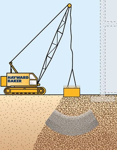
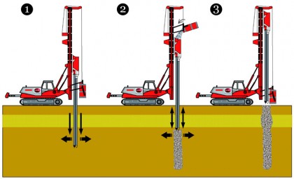
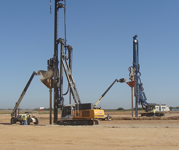
Vibro-compaction and vibro-replacement
Vibrators are generally attached to the top steel sections which are lowered into the ground. The dominant direction of vibration is vertical.
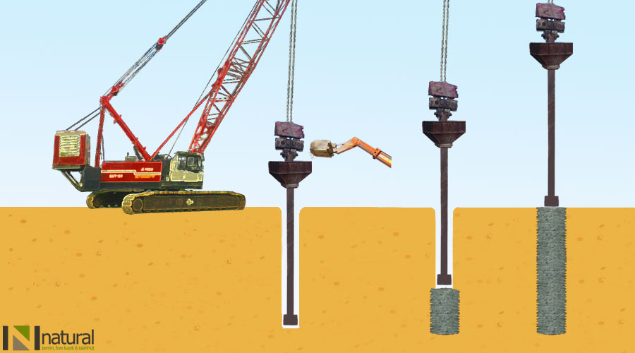
Stone Columns
A suitable technique of ground improvement for foundation on soft clay is to install vertical stone columns in the ground. This comes under vibro-replacement. Stone column method is essentially for soil reinforcement where the soft cohesive soil is replaced by compacted stone in pre-bored vertical holes within the soil. The stone columns serve two basic functions:
- providing reinforcement to the soil
- acting as vertical drains to allow subsoil consolidate to occur quickly under any given loading.
Greater stiffness of stone columns compared to that of the surrounding soil causes a large portion of the vertical load to be transferred to the columns. The entire soil below a foundation, therefore, acts as a reinforced soil with higher load carrying capacity than the virgin ground. Further, pore pressure dissipation by the radial flow accelerates the consolidation of the subsoil. Engelhardt et al. (1974) demonstrated the beneficial effects of stone columns by carrying out load tests in soft clay with and without stone column reinforcement.
Rammed stone column
This installation technique was proposed by Datye and Nagaraju (1977) and was developed by Nayak (1982). In this technique, the granular fill is introduced into a pre-bored hole and compacted by a heavy rammer through the borehole. The hole is made by using normal bored piling rig with winch, bailer and casing. For installing stone columns to greater depths, more than one piece of casing is used with the help of special quick release coupling. The casing maintains the stability of borehole. The stone columns are required to function as drain wells and it is advised not to use bentonite slurry for maintaining the stability of the borehole. Backfill material should be such that it gives high angle of internal friction under given energy of compaction. Sometimes the mixtures of stone aggregate and sand, generally in the proportion of 2:1, are used as backfill material. It is observed that sand is utilized mainly in filling the voids in gravel skeleton. Gravel backfill of the aggregate size generally recommended for gravel backfill is 75 mm to 2 mm. For good interlocking the gravel should preferably be angular shaped and well graded.
Comparison of construction technique
All installation techniques for stone columns in soft clay are self-adjusting, in the sense that enlargement of the column during ramming or vibration occurs depending on the soil consistency. Rammed stone columns have been used extensively in India. Nayak (1982) recommended that the angle of internal friction, may be as high as 45° for compacted granular fill in rammed stone column, whereas for vibro-floated stone column the angle ranges between 38°-42°.
Design of stone columns
Stone columns are typically selected to enhance bearing capacity, accelerate consolidation rate, increase shear strength, and reduce settlement and liquefaction potential, or any combination of the above. The design of stone column follows the basic principles (concepts) given below:
(a) Unit cell concept: For the purpose of settlement and stability analyses it is convenient to associate the tributary area of soil around each stone column with the column. Although the tributary area forms a regular hexagon about the stone column, it can be closely approximated as an equivalent circle having the same total area. The resulting equivalent cylinder of material having a diameter DJdc enclosing the tributary soil and one stone column is known as unit cell. The stone column is concentric with the exterior of the unit cell.
(b) Area replacement ratio: The volume of the soil replaced by stone columns has an important effect upon the performance of the improved ground. To quantify the amount of soil replacement the area replacement ratio, as, is defined as the fraction of soil tributary to the stone column replaced by the stone as as = AJA
Where: A is the area of stone column after compaction and A is the total area within the unit cell. Typical area replacement ratios used are in the range of 0.10 to 0.40.
Some works describe the ratio as as area improvement ratio, which is an inverse of the area replacement ratio Spacing and diameter: Stone column diameter varies between 0.45 and 1.2 m, but is typically in the range of 0.9 to 1.1 m for dry method, and somewhat larger for the wet method. Also, the diameter of the stone column depends on the strength and consistency of the soil. The diameter of stone column by varies from 0.6 m in stiff clay to 1.1 m in very soft clay. Rao and Ranjan (1985) reported that using the rammed technique, the installed pile diameter is about 20-25 % more than the initial diameter of the borehole. Nayak (1982) has given a chart to correlate the diameter of stone column and the undrained shear strength of soil.
Triangular, square and rectangular grid patterns are used with 'centre to centre' column spacing of 1.5 to 3.5 m. For footing support they are installed in rows or clusters. For both footings and wide area support, they should be extending beyond the loaded area. The design of stone column primarily involves determination of a suitable spacing of stone column for a chosen diameter and length of the stone column. It depends on the load bearing capacity of the foundation and the time for radial drainage. Mitchell and Katti (1981) have suggested typical pile spacing for rectangular and square grid. For triangular spacing, the reduction in settlement occurs only if the spacing of the stone column is close (s/d < 4) and installed to full depth of consolidating layer. However, too close spacing (s/d < 2) is not feasible from the construction point of view.
 Read also:
- soil densification by external forces
- Common distresses in asphalt pavements
- Solution of Soil Compaction Check Via The Voids Ratio
- Bituminous (Cementing) Stabilization
- Cost Estimating Process
 Share:
Follow our official Facebook page (@civilengineeringbible) and Twitter page (@CivilEngBible) and do not miss the best civil engineering tools and articles!