Different Concrete Prestressing Methods
Articles > Different Concrete Prestressing MethodsPrestress can be induced in the structure by various prestressing methods. Some of which are as follows:
Internal prestressing
In this system, a prestressing force is applied to the high tensile steel i.e. the steel reinforcement. It induces internal compressive stresses in concrete. it is the most commonly used method because of easy and accurate application. Internal prestressing can be done by two methods:
- Pre-tensioning
- Post-tensioning
External prestressing
This method is not commonly used. In this method, the prestressing is done by adjusting the external reactions (by introducing different support conditions). The externally prestressing system requires very much accuracy in the planning and applications. The method of prestressing involves pre-tensioning and post-tensioning methods.
Pre-tensioning method
In this method, prestressing is induced (the tendons are tensioned) before the concrete is placed. It is done in factories. In this method, the tendons are enclosed temporarily against some abutments and then they are pulled by using jack type devices. The concrete is placed while maintaining the tension. When concrete is hardened sufficiently, the tendons are released slowly or cut. This will transfer prestress from steel to concrete through bond.
This type of prestressing method is commonly used for small sized members like beams, slabs, piles, sleepers and electric poles, etc which can be casted easily in factories.
Advantages and disadvantages of pre-tensioning method of prestressing:
Pre-tensioning is done in the factories so it is more reliable and durable technique. But is used for smaller sections, so heavier and longer sections cannot be prestressed. When cable is released or cut, after pre-tensioning it leads to more losses due to shortening. The shrinkage and creep losses are also more in pre-tensioning system.
Post-tensioning method
In this method, the prestress is induced or tendons are tensioned only after the concrete has hardened. In this system, the concreting is done first and a duct is formed in the member with tube or with a metal sheathe. When concrete has sufficiently hardened then tendons or cable is transferred from the tendon to the member through anchorage wedges. The space between the tendon and the duct is filled with cement grout.
Post tensioning method of prestressing is used for both precast and cast in situ construction. It is used for large span structures like bridges.
Advantages and disadvantages of post tensioning method:
- Post-tensioning can be done in factories and at the site also
- The loss of prestress is less as compared to pre-tensioning system.
- This method is used for large spans and heavily loaded structures.
The disadvantages of post tensioning method are that it is costly as compared to pre tensioning method because of use of sheathing.
The comparison between the pre tensioning and post tensioning method is as follows:
|
Sr. No. |
Pre-tensioning method |
Post tensioning method |
|
1 |
It is done in the factories thus suitable for precast construction works |
It can be done in factories as well as on the site |
|
2 |
Small sections are to be constructed |
Size of member is not restricted, long span bridges are constructed by post tensioning |
|
3 |
Loss of prestress is more (about 18 %) |
Loss of prestress is less (about 15 %) |
|
4 |
It is cheaper because the cost of sheathing is not involved |
It is costlier because of use of sheathing |
|
5 |
It is more reliable and durable |
The durability depends upon the two anchorage mechanism |
The different prestressing systems
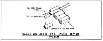
The Magnel Blaton system
In this system a cable of rectangular section is provided, which contains layers of wires 5 mm to 8 mm diameter. The wires are arranged with four wires per layer (up to sixteen layers deep for a cable of sixty four wires). The wires in the same layer and the wires in adjacent layers are separated with a clearance of 4 mm. the geometric pattern of the wires is maintained in the same form throughout the length of the cable by providing grills or spacers at regular intervals. The grills do not offer any appreciable frictional resistance to the wires which can be moved relative to each other during the tensioning process.
Gifford Udall System
This is earliest method in this method the wires are stressed and anchored one by one in separate cylinder using small wedging grips called Udall grips. Each grip consists of two half cones. The bearing plate bears against a thrust ring which is cast into the concrete. The duct end is encircled by a helix. Anchorages are supplied to suit the cables of 2, 4, 6 and 12 wires.
P.S.C. Monowire system
In this system also the wires are tensioned individually. The anchorages consist of a single piece collet sleeve wedging in a conical hole. A steel truncated guide leads each wire from the cable to the anchorage point along a gentle curvature. In addition to the guide a central block is also provided to anchor the central wires.
C.C.L. standard system
This is the anchor system where the wires are tensioned individually. As many wires as may be required (not exceeding 12) are used in a circular cable. The size of the duct depends on the number of wires – mm diameter for 8 wires - cable and 50 mm diameter for 12 wires cables. An interval of 600 mm spacers are provided to keep the wires separated and to prevent the outer wires from touching the sheathing. This not only reduces the friction but also allows satisfactory grouting. A special C.C.L. anchor grip is used to anchor each wire separately. The anchor grip consists of steel wedges which fit the over the wire and are recommended in a steel barrel having a tapered hole.
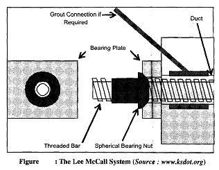
Lee-Mccall system
This is a system in which high tensile alloy steel bars are used as the prestressing tendons. These bars are provided in 22 mm, 25 mm, 28 mm and 30 mm diameter and in lengths up to 20 meters. The anchoring of the bars is done by screwing special threaded nuts. The nuts bear against a distribution plate provided at the end of the beam.
Chemical Prestressing
This is a method of prestressing using expanded cement. A concrete member made by using expanding cement is held at both its ends by rigid supports. As the concrete tends to expand a prestress is induced in the members. In an alternative method a concrete member is made using ordinary cement. At each end a gap is left between the end and a rigid support. Now the gap is filled with expanding cement. As this filler cement tends to expand a prestress is induced in the member.
 Read also:
- What is the difference between Hoyer system and Freyssinet system of Prestressing?
- Difference Between RCC and Prestressed Concrete
- Full Description of Types of Concrete Additions
- Factors of Safety for Cantilevered Sheet Pile Walls
- Distance Measurement
 Share:
Follow our official Facebook page (@civilengineeringbible) and Twitter page (@CivilEngBible) and do not miss the best civil engineering tools and articles!