Circular Arc Failure of Slope Analysis
Courses > Soil Mechanics > Slope Stability > Circular Arc Failure of Slope Analysis Introduction
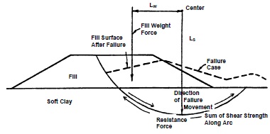
Experience and observations of failures of embankments constructed over relatively deep deposits of soft soils have shown that when failure occurs, the embankment sinks down, the adjacent ground rises and the failure surface follows a circular arc as illustrated in Figure below.
 Concepts and Formulas
At failure the driving and resistance forces act as follows:
- The force driving movement consists of the embankment weight. The driving moment is the product of the weight of the embankment acting through its center of gravity times the horizontal distance from the center of gravity to the center of rotation (LW).
- The resisting force against movement is the total shear strength acting along the failure arc. The resisting moment is the product of the resisting force times the radius of the circle (LS).
The factor of safety against slope instability is equal to the ratio of the resisting moment to
driving moment.
Failure takes place when the factor of safety is less than 1, i.e., the driving moment > resisting moment.
Simple Rule of Thumb for Factor of Safety:
A rule of thumb based on simplified bearing capacity theory can be used to make a preliminary "guestimate" of the factor of safety (FS) against circular arc failure for an embankment built on a clay foundation without presence of free water. The rule of thumb is as follows:
Where: c = unit cohesion of clay foundation soil (psf); γFill = unit weight fill (pcf); HFill = height of fill (feet)
Since the rule of thumb assumes that there is no influence from groundwater, c and γFill are effective stress parameters.
 The factor of safety computed by using this rule of thumb should never be used for final design. This simple equation obviously does not take into account such factors as fill strength or fill slope angle and does not identify the location of a critical failure surface. If the factor of safety computed by using the rule of thumb is less than 2.5, a more sophisticated stability analysis is required.
However, this rule of thumb can be helpful very early in the design stage to make a quick preliminary check on whether stability may be a problem and if more detailed analyses should be conducted. It can also be of use in the field while borings and sampling are being performed. For example, if in-situ vane shear tests are being carried out as part of the field investigation for a proposed embankment, the geotechnical specialist can use the vane strength with the equation above to estimate the FS in the field. This estimate can aid in directing the drilling, sampling, and testing program while the drill crew is at the site and help insure that critical strata are adequately explored and sampled. Finally, the FS calculated by the rule of thumb can be used to check for gross errors in computer output or input.
Stability Analysis Methods (General):
There are several available methods that can be used to perform a circular arc stability analysis for an approach embankment over soft ground. The simplest basic method is known as the Normal or Ordinary Method of Slices, also known as Fellenius’ method or the Swedish circle method of analysis. The Ordinary Method of Slices can easily be performed by hand calculations and is also a method by which the computation of driving and resisting forces is straightforward and easily demonstrated. For this method, the failure surface is assumed to be the arc of a circle as shown in Figure 6-7 and the factor of safety against sliding along the failure surface is defined as the ratio of the moment of the total available resisting forces on the trial failure surface to the net moment of the driving forces due to the embankment weight, that is:
Note that since the method consists of computing the driving and resisting forces along the failure arc, the moment arm R is the same for both the driving and resisting forces. Thus, the above equation reduces to:
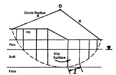
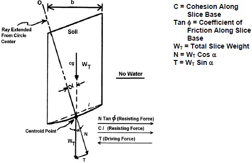
For slope stability analysis, the mass within the failure surface is divided into vertical slices as shown in Figures above. A typical vertical slice and its free body diagram is shown in Figure below for the case where water is not a factor.
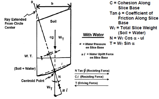
The case with the presence of water is shown in Figure below.
The following assumptions are then made in the analysis using Ordinary Method of Slices:
1- The available shear strength of the soil can be adequately described by the Mohr-Coulomb equation:
where:
τ = effective shear strength
c = cohesion component of shear strength
(σ - u) tan φ = frictional component of shear strength
σ = total normal stress on the failure surface at the base of a slice due to
the weight of soil and water above the failure surface
u = water uplift pressure against the failure surface
φ = angle of internal friction of soil
tan φ = coefficient of friction along failure surface
2- The factor of safety is the same for all slices.
3- The factors of safety with respect to cohesion (c) and friction (tan φ) are equal.
4- Shear and normal forces on the sides of each slice are ignored.
5- The water pressure (u) is taken into account by reducing the total weight of the slice by the water uplift force acting at the base of the slice.
The equation above is expressed in terms of total strength parameters. The equation could easily have been expressed in terms of effective strength parameters. Therefore, the convention to be used in the stability analysis, be it total stress or effective stress, should be chosen and specified. In soil problems involving water, the engineer may compute the normal and tangential forces by using either total soil weights and boundary water forces (both buoyancy and unbalanced hydrostatic forces) or submerged (buoyant) soil weights and unbalanced hydrostatic forces. The results are the same. When total weight and boundary water forces are used, the equilibrium of the entire block is considered. When submerged weights and hydrostatic forces are used, the equilibrium of the mineral skeleton is considered. The total weight notation is used herein as this method is the simplest to compute.
Ordinary Method of Slices - Step-By-Step Computation Procedure:
To compute the factor of safety for an embankment by using the Ordinary Method of Slices, the step-by-step computational procedure is as follows:
Step 1- Draw a cross-section of the embankment and foundation soil profile on a scale of either 1-inch = 10 feet or 1-inch = 20 feet scale both horizontal and vertical.
Step 2- Select a circular failure surface
Step 3- Divide the circular mass above the failure surface into 10 - 15 vertical slices as illustrated in Figure below
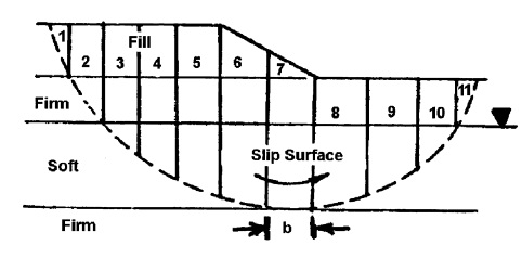
To simplify computation, locate the vertical sides of the slices so that the bottom of any one slice is located entirely in a single soil layer or at the intersection of the ground water level and the circle.
Locate the top boundaries of vertical slices at breaks in the slope. The slice widths do not have to be equal. For convenience assume a one-foot (0.3 m) thick section of embankment. This unit width simplifies computation of driving and resisting forces.
Also, as shown in figures above the driving and resisting forces of each slice act at the intersection of a vertical line drawn from the center of gravity of the slice to the failure circle to establish a centroid point on the circle. Lines (called rays) are then drawn from the center of the circle to the centroid point on the circular arc. The α angles are then measured from the vertical to each ray.
When the water table is sloping, use Equation 6-16 to calculate the water pressure on the base of the slice:
where: αw = slope of water table from horizontal in degrees.
hw = depth from ground water surface to the centroid point on the circle.
Step 4- Compute the total weight (WT) of each slice.
For illustration, the resisting and driving forces acting on individual slices with and without water pressure are shown on Figures above.
To compute WT, use total soil unit weight, γt, both above and below the water table.
WT = γt × Average Slice Height × Slice Width
Step 5- Compute frictional resisting force for each slice depending on location of ground water table.
N = total normal force acting against the slice base
N′ = effective normal force acting against the slice base
WT = total weight of slice (from Step 4 above)
α = angle between vertical and line drawn from circle center to midpoint (centroid) of slice base (Note: α is also equal to the angle between the horizontal and a line tangent to the base of the slice)
u = water pressure on the base of the slice = average height of water, hw × γw. Use γw = 62.4 pcf (9.8 kN/m3)
l = arc length of slice base. To simplify computations, take l as the secant to the arc.
u l = water uplift force against base of the slice per unit thickness into the plane of the paper.
φ = internal friction angle of the soil.
tan φ = coefficient of friction along base of the slice.
Note that the effect of water is to reduce the normal force against the base of the slice and thus reduce the frictional resisting force. To illustrate this reduction, take the same slice used in Step 4 and compute the friction resistance force for the slice with no water and then for the ground water table located 5 feet above the base of the slice.
Step 6- Compute cohesive resisting force for each slice.
c = cohesive soil strength
l = length of slice base
Step 7- Compute tangential driving force, T, for each slice.
T is the component of total weight of the slice, WT, acting tangent to the slice base.
T is the driving force due to the weight of both soil and water in the slice.
Step 8- Sum resisting forces and driving forces for all slices and compute factor of safety.
Slope stability guidelines for design:
| Foundation Soil Type |
Type of Analysis |
Source of Strength Parameters | Remarks |
|---|---|---|---|
| Cohesive | Short-term (embankments on soft clays – immediate end of construction – φ = 0 analysis). |
|
Use Bishop Method. An angle of internal friction should not be used to represent an increase of shear strength with depth. The clay profile should be divided into convenient layers and the appropriate cohesive shear strength assigned to each layer. |
| Stage construction (embankments on soft clays – build embankment in stages with waiting periods to take advantage of clay strength gain due to consolidation). |
|
Use Bishop Method at each stage of embankment height. Consider that clay shear strength will increase with consolidation under each stage. Consolidation test data needed to estimate length of waiting periods between embankment stages. Piezometers and settlement devices should be used to monitor pore water pressure dissipation and consolidation during construction. | |
| Long-term (embankment on soft clays and clay cut slopes). |
|
Use Bishop Method with combination of cohesion and angle of internal friction (effective strength parameters from laboratory test). | |
| Existing failure planes |
|
Use Bishop, Janbu or Spencer Method to duplicate previous shear surface. | |
| Granular | All types | Obtain effective friction angle from charts of standard penetration resistance (SPT) versus friction angle or from direct shear tests. | Use Bishop Method with an effective stress analysis. |
Note: Methods recommended represent minimum requirement. More rigorous methods such as Spencer’s method should be used when a computer program has such capabilities.Remarks on Safety Factor:
For side slopes of routine highway embankments, a minimum design safety factor of 1.25 as determined by the Ordinary Method of Slices is used. For slopes that would cause greater damage upon failure, such as end slopes beneath bridge abutments, major retaining structures, and major roadways such as regional routes, interstates, etc., the design safety factor should be increased to at least 1.30 to 1.50. For cut slopes in fine-grained soils, which can lose shear strength with time, a design safety factor of 1.50 is desirable.
 Watch Videos
 Solved sample problems
 Download Files
 Read also
- Critical Failure Surface
- Infinite Slope Analysis
- Top software for Geotechnical Engineers
- Terzaghi's Method
- Effects of Water on Slope Stability
 Share
Share
Follow our official Facebook page (@civilengineeringbible) and Twitter page (@CivilEngBible) and do not miss the best civil engineering tools and articles!